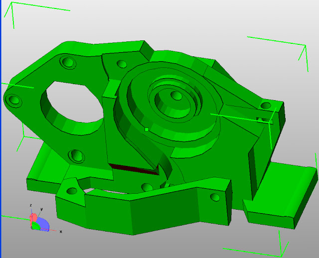
3DR Part 4 ! (long awaited... Firmware)I may have redefined the term 'coming soon' for this post, but it's here now, I hope you find it useful.
I had around 200+ messages about when part 4 would be up, most in the last week! I expect more people have some time off over Christmas to tinker, so obviously people have questions and are a bit stuck with Firmware and Calibration, if you have anything else I have not covered or if you need video clips or more images, just let me know and I'll update the post. I have tried to take it right back to the start, hopefully it's enough to get you up and running.
I scattered it with a few of the other things I have been doing in the last few months. So many things to share at the moment, I will aim to find some more time over Christmas to try and give an update on all the projects, events and work ongoing and coming up in the new year.
In Part 1 I introduced the 3DR Delta printer, the 3D printed elements and a list of the parts you would need to source, to build one yourself.
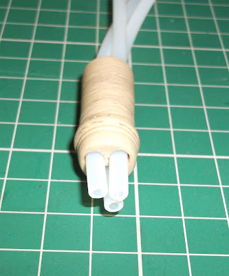
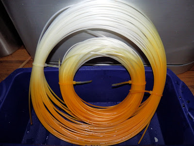
In Part 2 we looked at the preparation of parts, how the printer is assembled and stringing our Spectra Line In Part 3 we examined the electronics, wiring and the hot-end / extruder
Last few build questions - Another great BOM for 3DR is also now available, many thanks to Greg (gbathree)
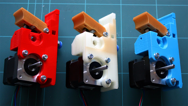
Over HereA few people have asked if different sized / lower power motors could be used on 3DR, yes you can and I also designed the motor mounts to accept both NEMA17 and NEMA14 motors. I tried a NEMA14 1.2A motor and it worked fine, saves some weight but they usually cost more than a standard sized NEMA17.
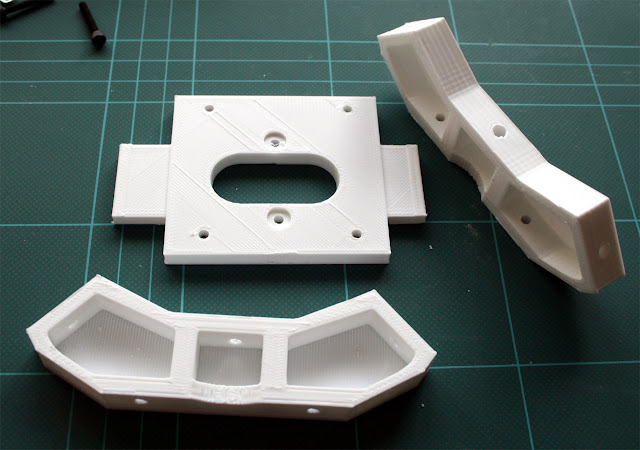
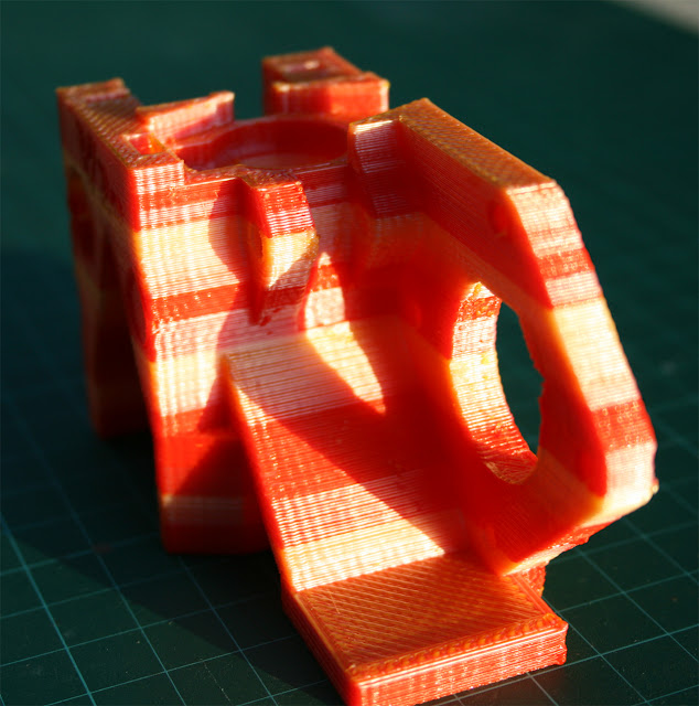
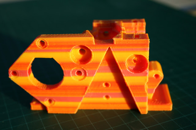
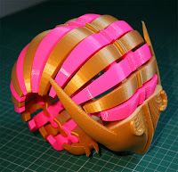
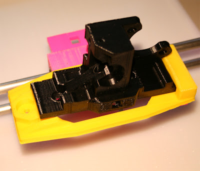
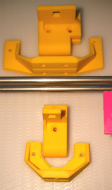
3DR Printed Parts - 3DR is still quite new, and the printed parts set can take a while to print out unless you have a fast and good quality printer :) but many are starting to appear in the world now, thanks to anyone who built one up, I hope it's working well for you.
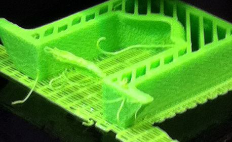
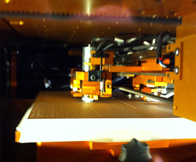
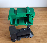
I have managed to print off a few sets for people, this set in Black and Gold went to a local maker who lives just a few miles from me, hopefully it will be running before Christmas.
If you are having problems getting hold of a set of parts, send me a message and I will try to help.
I get asked a lot about building
Bigger Delta printers. - Going higher is not a mystery you just extend everything taller. Going wider in X and Y is also quite easy, you just need to also extend the print arms. General relation in size of these arms is the horizontal distance between the vertical posts x 0.8
Eg - If you had a measurement of 600mm between two of the three posts a good arm length would be 600x0.8 = 480mm eye to eye.
If you make the arms longer you can print more outside of the vertical posts, That gets interesting when you have a really big platform because you have much more space to potentially use outside of the vertical posts, but it also uses up more vertical space with longer arms than you really need. Also be careful not to hit into these posts if you print very big things, most firmwares are dumb and do not know that you have vertical posts in the way of the printer's build envelope.
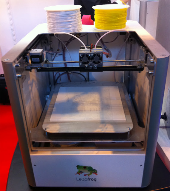
And if you want to see a massive Delta, take a look at the Wasp Ceramic printer, this was on display and working at the 3D Printshow last month in London. It's a real monster, and I'm not exactly sure how they managed to get Health and Safety permission to have this running in the open! but it was one of the most impressive things at the show.
WASP - Big clay delta printer at the 3D Printshow London
Just for the scale of it - one with people - it's massive!
Using a combination of multiple fans and Halogen lamps to assist with the firming up the clay layer as it prints, the results were nice, but you can still see the pulsing effect of the extrusion system.
Printing in Clay - Using compressed Air to transport the clay under pressure, and a small auger at the nozzle to control the flow of material, it was working well, but how long the auger will last with abrasive clay...
Another big machine is the
Deltatower again a nice design.
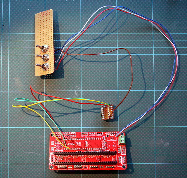
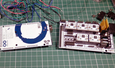
RepRap and other 3D printing electronics quite commonly use versions of the Arduino electronics as their basis, some newer sets are starting to use ARM based electronics, these will most often use other types of Firmware. For this tutorial we are using Arduino based RUMBA and also looking at RAMPS as the electronics for 3DR.
People seem to be having various issues with RUMBA. These seem to range from connecting correctly (or not) to the PC/Win/Mac/Linux and others with uploading firmware and a few with getting it operating correctly after downloading the firmware.
A few people have commented (me included in Issue 2 or the RepRap magazine, electronics article) that the software implementation of the FTDI device on the RUMBA board may not work as well as the generic Arduino version. In the end I didn't change my boards, but a few people have used the Arduino serial code and that seemed to solve a number of issues with connection.
Another point seems to be with using long USB cables (may well be connected to the above) - I always use the LCD and SD card for printing, so almost never have a USB cable fitted, if you are running from USB than try to use a 1.5M or shorter cable.
I will try to go over as many things as I can here, and see if it helps, if I miss out an important step and you can't find it on my blog or generally on the net, then please ask and I will add more details or expand on things if they are not clear.
Also the Firmware - Marlin changes all the time, so depending if you are using my (now very old) branch for 3DR or the now 'standard' Marlin with Delta support already enabled you may have a few differences with config's etc.
For consistency I'm going to be talking about
my modified version over on Github here, I know it's a few months old and does not have auto-leveling and it has a few minor niggles, but it works well for me using 3DR with the XXL LCD screen.
Firstly be aware that there are some incorrect and dodgy Pins.h files for RUMBA, I made changes to Marlins Pins.h file after initially having issues, so do check you have the correct pin-outs for RUMBA before trying to use it.
I believe my branch of Marlin Firmware for 3DR is correct in this respect.
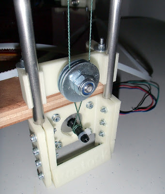
Before we dive into Firmware settings, do check your wiring, and make sure you have the X EndStop going to the X motor, Y EndStop going to Y and Z to Z. if you are unsure just be aware that you may need to check and swap them during the homing sequence. Especially if you see motors still running after it looks like they have hit the EndStop positions.
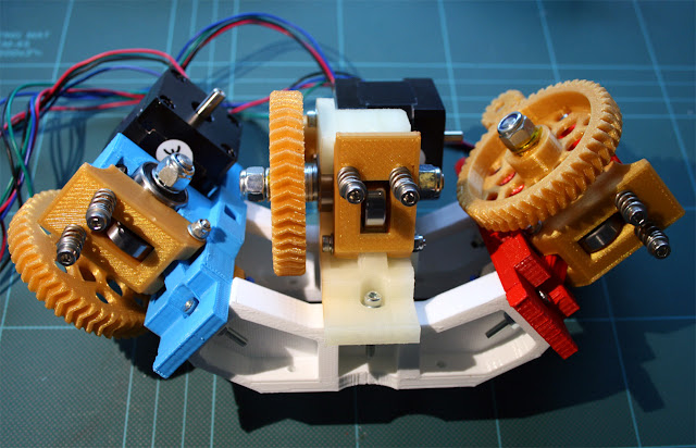
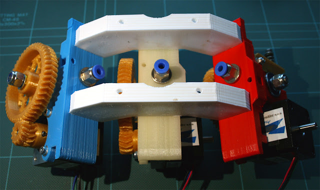
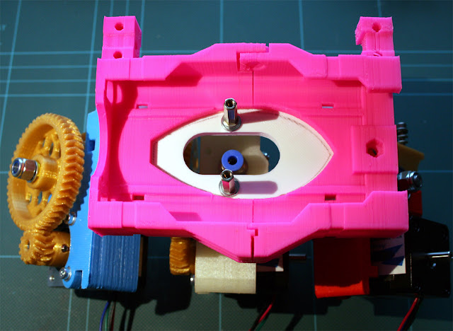
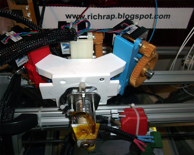
X = front left tower / Y = front right tower / Z = back middle towerFor anyone that already understands the Marlin firmware, one quick point - The first thing I need to say is that my Extruder esteps in the firmware above are for a mixing setup, so the 120 steps per unit (mm) is too low for the normal 3DR single extruder, you will need to set this to be around 270 steps per unit (mm) - this also assumes you are using x8 microsteps on your extruder double that if you are running x16 microsteps.
If that didn't make sense, read on, I'll try to explain how to use Marlin firmware below -
Install Software - If you have not already, download and Install the
Arduino IDE enviroment from Here - You want Version 0023 for most versions of 3Dprinting Firmware out there. Some do work with the newer V 1.X versions.
Arduino based electronics use a USB port for firmware upload and communication to the computer. This USB port is configured as an old industry standard RS232 serial port. Therefore the operating system may require a device driver to be installed so you can communicate with the electronics and the Arduino IDE can download code. These are normally FTDI Drivers found in the /Drivers directory of the Arduino IDE, if the operating system is looking for them, point to the drivers directory and they should install.
Next you need to download some Firmware to run on the electronics,
My version for 3DR can be found here - Click on the 'Download ZIP' on the right hand side of the screen.
Extract to a directory and load up the Arduino V0023 IDE.
Then you will need to Open Marlin firmware in the Arduino IDE - go to the Marlin directory \MARLIN_FIRMWARE_for_3DR_V2-master\Marlin\ and load the file
Marlin.pde (processing source code)
After you select that file all the software source will be loaded into the Arduino IDE as above.
The Tabs along the top allow you to select the different files used to make up the Marlin firmware.
I'm not going to go too deep into every function and operation of Marlin, at this point let's just go over the main areas you need to know and files / settings you may need to change depending on your configuration and setup.
The main file to edit in Marlin is
Configuration.h this is called a header file and it contains many of the key settings to describe to the firmware how your 3D printer's mechanical and electronic systems are setup.
As we go down the file I will highlight areas of interest and settings you may need to check or change for your 3DR machine.
Anything in
blue is from the firmware, anything after a
// is a comment and has no action in the firmware, it is simply a note to remind you of things or explain the setting etc.
#define STRING_CONFIG_H_AUTHOR "(RichRap, 3DeltaRap)" //Who made the changes.This is sign-on message, feel free to change the text in brackets to something you want to see.
#define BAUDRATE 250000//#define BAUDRATE 115200The
BAUDRATE is the speed that the RepRap electronics FTDI serial port will connect and talk to the computer, it's running at 250k baud (speed) at the moment, if you wanted to run at another standard rate 115k2 you would remove the
//from the second line shown above and add
// to the first line, this enables one setting and and comments out the original settings.
//// The following define selects which electronics board you have. Please choose the one that matches your setup// 10 = Gen7 custom (Alfons3 Version) "https://github.com/Alfons3/Generation_7_Electronics"// 11 = Gen7 v1.1, v1.2 = 11// 12 = Gen7 v1.3// 13 = Gen7 v1.4// 3 = MEGA/RAMPS up to 1.2 = 3// 33 = RAMPS 1.3 (Power outputs: Extruder, Bed, Fan)// 34 = RAMPS 1.3 (Power outputs: Extruder0, Extruder1, Bed)// 4 = Duemilanove w/ ATMega328P pin assignment// 5 = Gen6// 51 = Gen6 deluxe// 6 = Sanguinololu < 1.2// 62 = Sanguinololu 1.2 and above// 63 = Melzi// 7 = Ultimaker// 71 = Ultimaker (Older electronics. Pre 1.5.4. This is rare)// 8 = Teensylu// 80 = Rumba (RepRapDiscount)// 81 = Printrboard (AT90USB1286)// 82 = Brainwave (AT90USB646)// 9 = Gen3+// 70 = Megatronics// 90 = Alpha OMCA board// 91 = Final OMCA board// 301 = Rambo
#ifndef MOTHERBOARD#define MOTHERBOARD 80#endifThe above is defining to the firmware what electronics you have installed. At the moment the Definition
MOTHERBOARD (that is used in the rest of the firmware as a 'flag') is set to
80, if we look in the commented list above you will see that
80= Rumba electronics.If you are running RAMPS (1.3 with a single extruder), then change the line
#define MOTHERBOARD 80 to be
#define MOTHERBOARD 33Hopefully this is making sense to anyone not familiar with Marlin Firmware, if you are, you may have already done this and want to skip most of the next section.
In the delta settings are comments explaining what the settings are doing, only change them if you understand what you are doing or have read more about them in the
Delta RepRap forums or
Deltabot Google Group #define DELTA_DIAGONAL_ROD 153.0 // mmMeasure the exact distance between the mounting holes/posts of the 6 rods, they should all be identical, enter the measurement here.
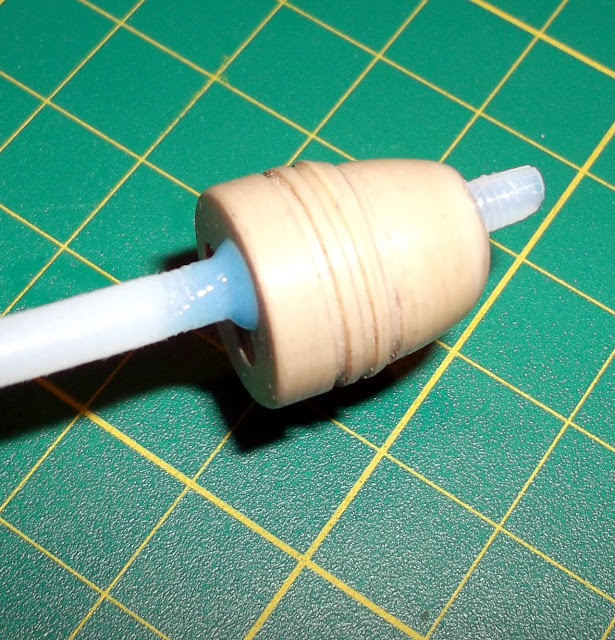
#define DELTA_SMOOTH_ROD_OFFSET 111.9 // mm You will need to adjust this number when you tune the printing surface. If you lower this number the hot end will rise when it's in the middle of the build plate. When you have the correct distance set to the middle point for printing you may be too high or low at the outer edges, this is where you need to tuns this figure to get a flat print envelope across the surface.
// Horizontal offset of the universal joints on the end effector.#define DELTA_EFFECTOR_OFFSET 33.0 // mm // Was 42.0 mmYou should not need to change this unless you use a different carriage platform design or assemble it in a different way than described in previous parts of this tutorial.
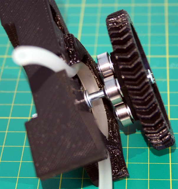
// Horizontal offset of the universal joints on the carriages. (This is measured from the edge of the M6mm Rod to the cent of universal joint, 14mm on Mini Delta (3DR)#define DELTA_CARRIAGE_OFFSET 14.0 // mm // Was 25.0 // mmThis you may need to change if you are using a different linear bearing / rod size / bushing / or a modified carriage design. If not, 14.0mm should be correct for 3DR using normal carriages and LU6UU bearings.
//===========================================================================//=============================Thermal Settings ============================//===========================================================================////--NORMAL IS 4.7kohm PULLUP!-- 1kohm pullup can be used on hotend sensor, using correct resistor and table////// Temperature sensor settings:// -2 is thermocouple with MAX6675 (only for sensor 0)// -1 is thermocouple with AD595// 0 is not used// 1 is 100k thermistor - best choice for EPCOS 100k (4.7k pullup)// 2 is 200k thermistor - ATC Semitec 204GT-2 (4.7k pullup)// 3 is mendel-parts thermistor (4.7k pullup)// 4 is 10k thermistor !! do not use it for a hotend. It gives bad resolution at high temp. !!// 5 is 100K thermistor - ATC Semitec 104GT-2 (Used in ParCan) (4.7k pullup)// 6 is 100k EPCOS - Not as accurate as table 1 (created using a fluke thermocouple) (4.7k pullup)// 7 is 100k Honeywell thermistor 135-104LAG-J01 (4.7k pullup)//// 1k ohm pullup tables - This is not normal, you would have to have changed out your 4.7k for 1k// (but gives greater accuracy and more stable PID)// 51 is 100k thermistor - EPCOS (1k pullup)// 52 is 200k thermistor - ATC Semitec 204GT-2 (1k pullup)// 55 is 100k thermistor - ATC Semitec 104GT-2 (Used in ParCan) (1k pullup)
#define TEMP_SENSOR_0 1#define TEMP_SENSOR_1 0#define TEMP_SENSOR_2 0#define TEMP_SENSOR_BED 0The next thing to check is your thermistor / thermocouple setting. As we did with the electronics you need to select the type of temperature sensor you have fitted to your hot-end. If you decide to install a heated bed, you also need to change the
TEMP_SENSOR_BED 0#define PID_MAX 190 // limits current to nozzle; 255=full current //RichRapIn the PID settings you may want to limit the power available to your hot-end (if you have installed a Cartridge heater) or set this to maximum (if you are using a 6.8R resistor as the heating element) I have a 40W cartridge heater fitted and so set the Max to 190 to limit the power, I don't want it going too high if it stays on for any reason.
// 3DR - RichRap// #define DEFAULT_Kp 12.83// #define DEFAULT_Ki 0.81// #define DEFAULT_Kd 50.87// Above settings for 3DR - Jhead 0.35mm and 20w Heat cartridge limited PWM
// For RichRap V2 3DR Machine - with Dual feed head// bias: 102 d: 87 min: 147.00 max: 153.04// Ku: 36.66 Tu: 31.85// Clasic PID// Kp: 22.00// Ki: 1.38// Kd: 87.57 #define DEFAULT_Kp 22.00 #define DEFAULT_Ki 1.38 #define DEFAULT_Kd 87.57// Above settings for 3DR - Jhead 0.35mm and 20w Heat cartridge limited PWM
As a default I have my mixing extruder set in the firmware, so for the PID settings if you are using a J-head enable the first set and comment out the dual feed head.
You will need to run M303 as an Autotune command to get your own specific set of PID values to enter in here, only do that when you are ready to print, then enter the numbers and re-compile and download.
You can do the same with the Heated bed if you have one installed and are using PID control for it. I tend to use Bang-Bang control for the heatbed on other machines.
Motor direction -
You can invert the direction of any stepper motor used in the printer - the list below shows true or false
#define INVERT_X_DIR false //
#define INVERT_Y_DIR false //
#define INVERT_Z_DIR false //
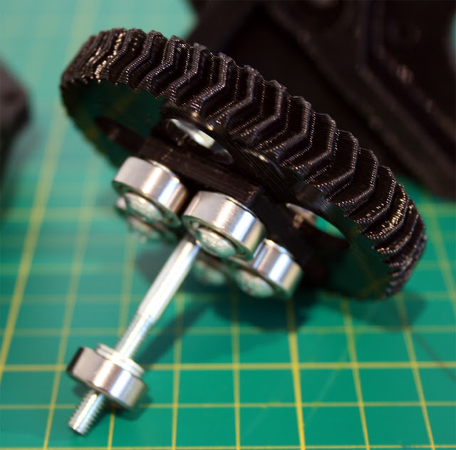
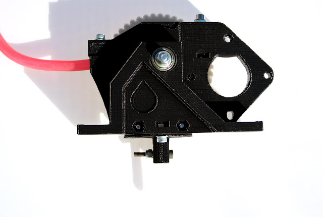
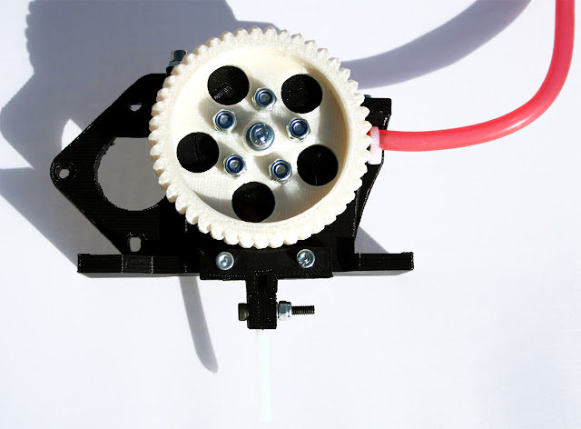
#define INVERT_E0_DIR false // False for 3DR V2 Gregs Geared Extruder - note wiring on motor is correct
#define INVERT_E1_DIR true //
#define INVERT_E2_DIR true //
If you wanted to change the direction of X, maybe because you wired it backwards or wrapped the spectra string in the opposite direction to the other two motors, you can simply change #define INVERT_X_DIR false to be #define INVERT_X_DIR true
#define EXTRUDE_MINTEMP 160
Minimum extruder temperature is the next setting to check. If you are going to be printing very small parts, fine detail, you can print at 160 or lower with PLA, so it's possible you may want to lower this number a little more. to be safe I tend to print at 165 or higher for most things.
const bool X_ENDSTOPS_INVERTING = true; // set to true to invert the logic of the endstops. //Richrap changed from false
const bool Y_ENDSTOPS_INVERTING = true; // set to true to invert the logic of the endstops. //Richrap changed from false
const bool Z_ENDSTOPS_INVERTING = true; // set to true to invert the logic of the endstops. //Richrap changed from false
Always a good one to check in any firmware, make sure your end-stops activate with the correct orientation, or your machine will not respond to commands.
#define MANUAL_Z_HOME_POS 187.5 // For V2 = WithDual Feed RichRap Hot-End = 187.6mm - with Dibond bed and single layer of blue tape
// For V2 = with 3mm bed and 1 layer of Blue tape = 195mm - using a J-head
// For V1 3DR Below
// was 211 - Distance between nozzle and print surface after homing. The 0.5mm was added after carefull leveling and adjustments.
// 211.5 = with a 2.64mm wooden base + Blue tape
// 211.4 = 3mm base + Blue tape
The Manual home Z position is basically the maximum distance for the hot-end home point to the print bed. you need this set to within 2mm and you can do fine adjustments using the Hall effect end-stop adjustment pots on each axis to get the nozzle level.
NOTE: - Most of the settings below when they are in a format like this relate to the following settings of the 3D printer - {X Axis, Y Axis, Z Axis, Extruders}
#define DEFAULT_AXIS_STEPS_PER_UNIT {55.5, 55.5, 55.5, 120}
Steps per unit will depend on the micro-stepping you have used, and any gearing differences used on the extruder. The last number 120, is for my Mixing extruder so if using the 3DR geared extruder set this to between 260 to 290 depending on the type, shape and style of hobbed bolt / drive bolt you are using on the extruder.
#define DEFAULT_MAX_FEEDRATE {380, 380, 380, 29} Feel free to home a bit faster if you like. The Extruder max feedrate is interesting, you want this as fast as possible but not too fast so the extruder can't drive it. After much experience using this extruder and setting current limits of the NEMA17 motor (48mm long 2.5A version) for me the maximum speed to set in firmware is 32mm. I usually limit it to 29 as that's fast enough for most Bowden systems under 1000mm long.
You can increase the X,Y,Z feedrates, 500 to 800 should be workable, I run at 500 on my 3DR's now. if you want to experiment higher feel free! you will be shocked how fast travel and print moves are.
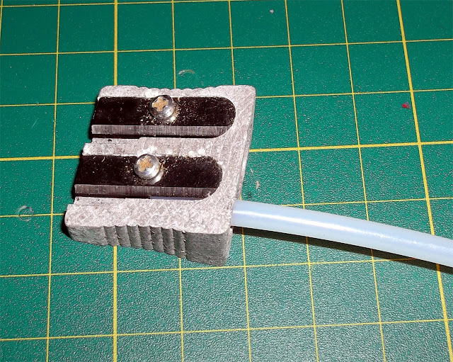
Top Tip - In Slic3r always make sure you set the extruder speed for retraction to 100+ or more, this way, only the firmware limits the speed, so when you slow down the overall print speed of the machine (easy to do with an LCD screen fitted) the extruder will not slow down on retractions. If you set the extruder speed in Slic3r to be 29mm/sec the it too slows down when you scale the overall speed of the machine. If you decide to try printing slowly and tiny things with a bowden setup, you need to keep up fast retractions and really lower the hot-end temperatures by quite a lot.
#define DEFAULT_ACCELERATION 380 // V1 was 380 / using 380 - (300 was ok, originally 400 ) X, Y, Z and E max acceleration in mm/s^2 for printing moves#define DEFAULT_RETRACT_ACCELERATION 380 // V1 was 380 / using 380 - (300 was ok, originally 400 ) X, Y, Z and E max acceleration in mm/s^2 for r retractsThese are safe acceleration speeds, you can go much faster if you wish, 3DR can handle it.
Both of the above will work at 10x the above 380 values (and higher if you want to experiment, this will seriously speed up 3DR - you will need a good extruder to keep up! and a print temperature of at least 218 Deg C for PLA)
#define DEFAULT_XYJERK 20.0 // (mm/sec) V1 was 20 / now using 18 for V2#define DEFAULT_ZJERK 20.0 // (mm/sec) V1 was 20 / now using 18 for V2#define DEFAULT_EJERK 15 // (mm/sec) // was 12 (8 was too slow) 12 was okThese are all safe values, feel free to experiment with them, but the acceleration and feedrates above should be experimented with first.
#define REPRAP_DISCOUNT_SMART_CONTROLLER //RichRap = enabled for RUMBAThis last section enables the RepRap Discount XXL LCD controller panel and SC card, highly recommended for 3DR operation.
Other Firmware files and settings for interest - You can compile and use the firmware at this point, but I just wanted to go over some of the other header files used in Marlin as some of you may have a use for them or want to change things / experiment.
Configuration_adv.hIn this file we have some more advanced settings, most you will never need to change, but some can tune your machine to be faster or easier to operate as you get more confident.
You can also set number of extruders enabled and change various aspects of temperature measurements and machine movement.
Pins.hThis file is really useful if you decide to add more or re-purpose parts of the electronics for different reasons. For example adding a camera trigger signal to a spare output pin on the electronics, here in Pins.h you can define the pin number for the rest of the code to use for that purpose. Other fans, or additional temperature sensors, maybe for measuring chamber temperature can be set here to match how you have wired them on the electronics.
* Do make sure you edit the correct part of the file, it needs to relate to the choice of electronics you selected in configuration.h above. For example if you search for
#if MOTHERBOARD == 80 you will get to the section defining the RUMBA pins - edit these as required when using RUMBA electronics.
Language.hIs useful if you are running the LCD screen and want to display details in a different language. 8 languages are supported at the moment, English tends to be set as the default.
All the other files and source-code used in Marlin can also be edited too, but it's really only advisable to do so if you understand more about how the system is running. It's very easy to break many things just by a tiny edit in the wrong place or an incorrect adjustment of a setting.
Compiling and uploading - After any changes made above, you need to save the changes, then compile the code and upload to the electronics before any changes you have made will take affect.
Connect your electronics board with the USB cable and if required make sure it has power applied -* note, some electronics can be powered up from the USB cable to update the program. Others you need to have the main power supply on to enable an update. Some also allow you to choose with a jumper setting or switch on the electronics board.
First we need to make sure that we select the correct Arduino type in the board list. Shown above we are selecting the Ardunio Mega 2560, this is often used on RAMPS, RUMBA and many other RepRap electronics. Some older versions of RAMPS may still use the Mega 1280, check what type you have and select the correct one.
Then also select the serial port your electronics are using, a list will be shown after you connect the electronics. It's different on PC's / Mac's and Linux, just be aware you need to select the correct communication port to enable uploading of firmware to the electronics.
To compile the code, make sure you save any changes then click on Verify/ Compile
If successful you will see the following comment in the window at the bottom of the Arduino window
You can then Click on the upload button, this is an arrow at the top pointing to the right.
Help! it's not compiling and it's giving me error messages - If for example we had an error, in this case I defined the electronics set to be 88 instead of 80 for RUMBA, because a Pin definition for Electronics type 88 has not been defined the compile process will fail.
The Arduino IDE tries to let you know what the problem is and will jump to the point of failure, unfortunately this is not always helpful as many things go wrong and it will jump you off to the last failure. What you normally need to look at is the first failure in the list.
In this case that first failure in the list is actually quite helpful
- /pins.h:1628:2: error: #error Unknown MOTHERBOARD value in configuration.hIt's basically telling you that it could not find a look-up table in Pins.h corresponding to the value you gave it, but that is because of an unknown value for MOTHERBOARD in configuration.h - that's exactly the error I inserted so fix that (back to 80) and it will now compile.
You will get similar error messages if you accidentally add notes without commenting them out, it tries to compile the notes and fails on the next part of real code it finds.
Top Tip - is to always have a backup of working firmware, if you mess up things so badly you can't work out what's going wrong, use the backup and start again.
Hopefully that allows you to upload some firmware to your 3DR, now lets do some basic calibration before we try to print anything.
For testing I'm going to use
Pronterface by Kliment, you can download it from GitHub hereYou also need some dependencies to be installed for Pronterface -
WindowsDownload the following, and install in this order:
- http://python.org/ftp/python/2.7.2/python-2.7.2.msi
- http://pypi.python.org/packages/any/p/pyserial/pyserial-2.5.win32.exe
- http://downloads.sourceforge.net/wxpython/wxPython2.8-win32-unicode-2.8.12.0-py27.exe
- https://pypi.python.org/packages/any/p/pyreadline/pyreadline-1.7.1.win32.exe
- http://pyglet.googlecode.com/files/pyglet-1.1.4.zip
For the last one, you will need to unpack it, open a command terminal, go into the the directory you unpacked it in and run python setup.py installFor other operating systems, check the Github page
Testing and calibrating - After getting the firmware installed on to your electronics, I would recommend the following process -
Manually move each arm / carriage one at a time towards the Hall-effect end stop (or switch/opto end-stop if you have used those) make sure the LED lights and at this point turn the pot on each hall-effect sensor board to be in the middle.
Move all three carriages down about 50mm from the end-stops.
If you have an LCD screen installed, click to the
Main Screen, navigate to
Prepare, then click on
AutoHome.
Be prepared to hit the stop button on the LCD panel or turn off the power if any of the carriages move down rather than up.
You can do the same with
Printer interface (pronterface) by connecting and clicking on the home all button.
What should happen is that all three carriages move up and each one will stop in turn when the end-stop is triggered.
If any one or all three move in the wrong direction (down) you can either (power down first) and rotate the 4 way motor connector on your electronics, or change the direction in configuration.h firmware. both will reverse the direction of the motor. (see above section showing
#define INVERT_X_DIR false // )
Hot-end - Next let us check that the hot-end is heating and temperature is being measured.
LCD screen, click to the
Main Screen, navigate to
Prepare, then click on
Preheat PLAOr in Pronterface click on the Set button shown above in orange - note the temperature is set to be 200 Degrees C (for PLA)
Heating of the hot-end should start and you should start seeing the temperature rise. If it is, then turn it off. If it's not check your wiring and make sure you have the thermistor / thermocouple connected to the correct pins on the electronics.
If it look like it's heating up and measuring the temperature rise, you can now run the hot-end auto-tune command M303.
To run the auto-tune command all you need to do is enter m303 and click send in pronterface.
This will start the auto-tune. The temperature will ramp up and down for a few cycles and then give you a set of (PID) figures specific to your particular setup and way you have installed it. These need to be entered in the firmware, re-compile and download, then you have a well tuned hot-end. This will help keep a stable temperature and have a good heating ramp up without too much overshoot of temperature.
Check the firmware section above with this code -
#define DEFAULT_Kp 12.83
#define DEFAULT_Ki 0.81#define DEFAULT_Kd 50.87It's important to do this m303 command, as every hot-end can give quite different results, even depending on how much insulation or tape you have used on the heater block can give different characteristics.
Bed leveling - Getting a level print bed and setting the correct distance for the three carriages can be a bit tricky, it's a simple process but many things can be out of alignment, so take your time and think logically about the process.
First try to measure and check you have somewhat of an equal distance on each tower between the tops and bottom printed parts. Loosen and tap level if not.
Try also to get the bed as level as possible, use a sheet of glass or Di-bond material as the print surface.
Use the printed bed clamps and fix it down flat.
With your carriages all parked at the top in the home positions, measure the distance between the nozzle and the build plate. Enter that number in the firmware
#define MANUAL_Z_HOME_POS 187.5You still need to tune each end-stop and possibly raise or lower the build surface, but I found the best way to do that was to start printing and see how far out it is by the first layer print.
First Print ! - I will be using
Slic3r and Pronterface for the calibration process.
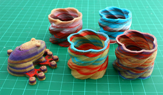
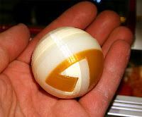
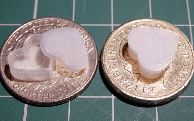
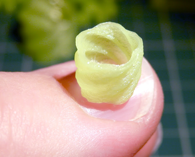
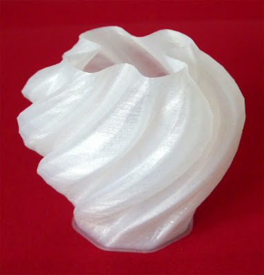
For a test print on a new Delta machine it's a good idea to print a flat circle plate. A pot object or anything that goes to about 80% of your build surface.
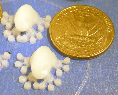
To start with you are only really interested in the outer perimeter and the centre.
An easy way to get a perimeter is to print a small round object (like the coin above) and set the loops to be 2 and distance from object to be around 50mm.
You will end up with G-code that will first draw two perimeters and then the coin in the middle.
It's a common problem that the outer perimeter is higher or lower than the middle, you may also not actually see this if you only print small objects, so it's well worth doing the perimeter and center test at the start to get the bed setting flat.
With the Delta settings in the firmware you are trying to make sure the hot-end distance from the bed is the same in the middle as it is at the outer edges.
To adjust this value for a dome or concave effect you need to change the following in firmware (Configuration.h) -
#define DELTA_SMOOTH_ROD_OFFSET 111.9 // mm As stated above in the firmware section if you lower this number the hot end will rise when it's in the middle of the build plate.
Print this Gcode and see what the perimeter looks like when it's being laid down on to the platform. You want an even pressure onto the bed all around the circle.
You can also adjust each delta column distance with the hall-effect end stops. Rotating the Pot counterclockwise will bring the carriage magnet closer to the sensor before detection which will raise the head on that column of the bed. Clockwise will lower the head.
Adjust for dome and distance of each carriage, and you should be able to get the print surface flat and ready for printing.
In the next Part of this guide we will look at using Slicer with 3DR and various types of materials to print along with different types of objects and support structures.
Top Tip - In Slic3r do remember that the settings you enter will normally be limited to the Firmware #defines and settings. When you start to print really fast, it's these firmware settings that control what print and travel speeds the 3Dprinter has, NOT Slic3r.Another really important point is the Cooling setting in Slic3r, if you enable this, then Slic3r itself will slow down the G-code, so you can enter print speeds of 1000mm/sec, but that's being ignored.
I must upload a video of aggressive Acceleration values set on 3DR, and only 60mm/sec Set in Slic3r - many people will look at it and think it's running at hundreds of mm/sec just because the firmware is not limiting the speeds in any significant way. If you speed up things as mentioned above you can try it for yourselves (on almost any printer - but Delta's have an advantage of a very light weight and fast moving print head)
It's one of the biggest myth's of 3D printing, when running really fast, speed set in the slicer application is not really what you are experiencing due to firmware or 'cooling' limiting.Heated Beds! -We have a heat-wave of hot beds being attached to 3DR (myself included) -
Cybug has done some really neat 3DR extenders to allow bigger print areas and a heated bed, this was the sort of thing I had in mind about 3DR being scalable, so great job for doing it and the colour scheme is cool!
Cybug - big and tall!
Cybug - bigger 3DR with silicone heated bed and glass print surface.
Richard Gain has also experimented with adding a silicone heated pad and cardboard insulation, these little 50W +12V pads are up for sale on Rich Gain's eMaker shop here
Richard Gain - heated bed for 3DR - 160mm round heated pad.
Photo by - German Palacio (FraNtik) of 3DR self-replicating ! - Nice
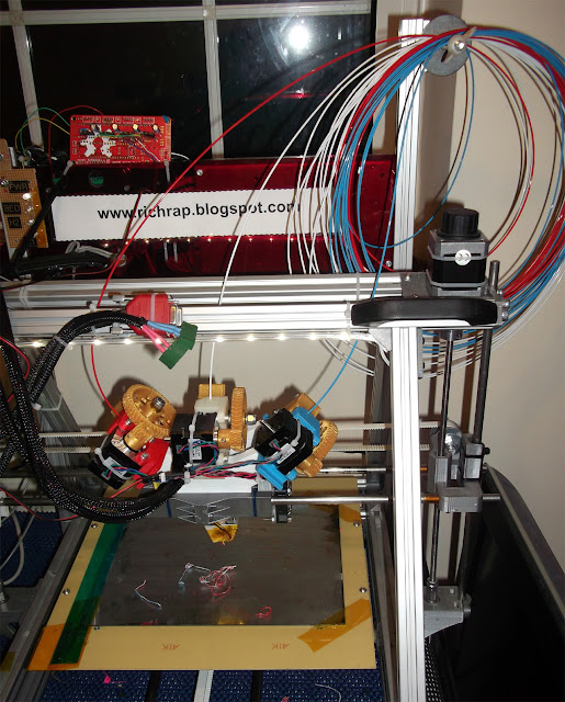
I have fitted a heated bed to a tall 3DR unit, this one is a 170mm print surface PCB, using around ~100 watts @12V.
It requires an additional mounting adapter but fits onto the standard 3DR with these small extra printed parts. For thermal resistance, print these in a PET material like Taulman T-glase or Colorfabb_XT or if you must, ABS.
Some thermal insulation below will keep heat away from the PLA of the 3DR.
If you are interested in using one of these heated beds, do let me know.
Other Upgrades - HeAdWaVe has produced a very nice RAMPS and fan adapter, and shared it over
on Thingiverse hereImages and RAMPS adapter design by HeAdWaVe.
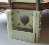
More 3DR style Machines - The 3DR simple design by JohnSL is coming along very well. - Image by JohnSL -
3DR Simple here You may also notice the jig measuring tool for setting rod lengths - this was designed by ichibey and is up on
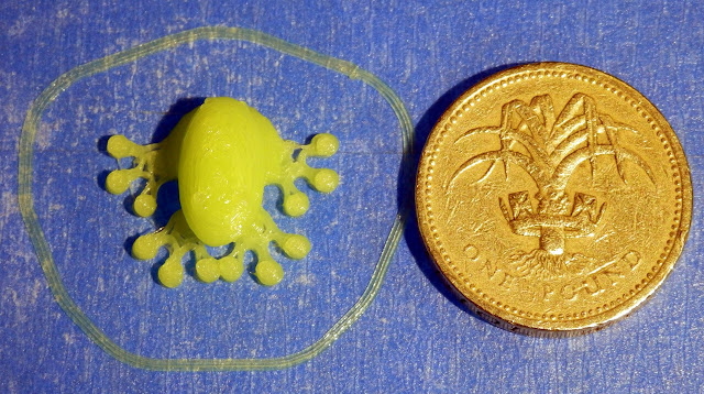
Thingiverse here.LISA Simpson concept by Nicholas Stewart - gotta love that name.
Nicholas Seward is contemplating a rather neat variant of the very printable Simpson (
LISA Simpson here)
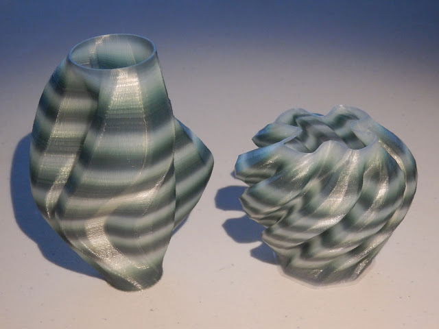
3DR Bamboo! - I finally made a 3DR with Bamboo and a really excellent new wood material from
Colorfabb called Woodfill. This material is a little like Laywood, but it does not change colour when heated and I found it easier to print with, more flexible and producing stronger printed objects.
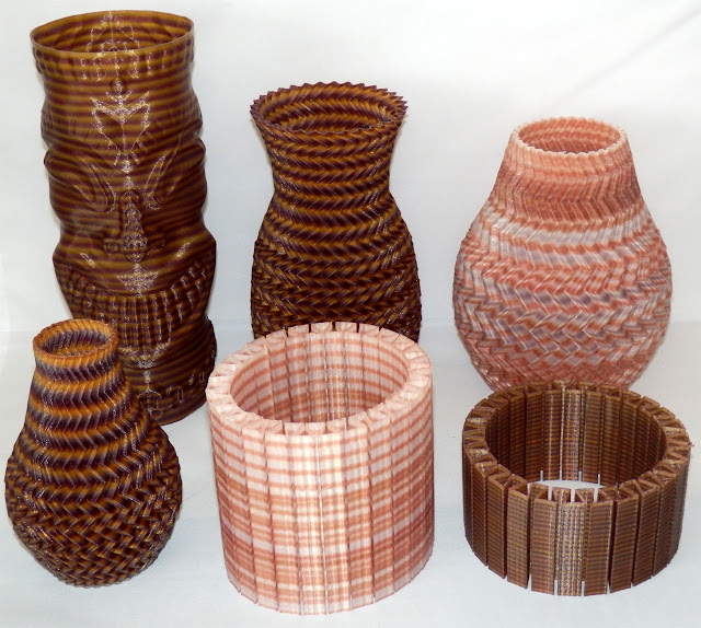
3DR-ECO - Bamboo Canes and Woodfill - finished with polyurethane varnish.
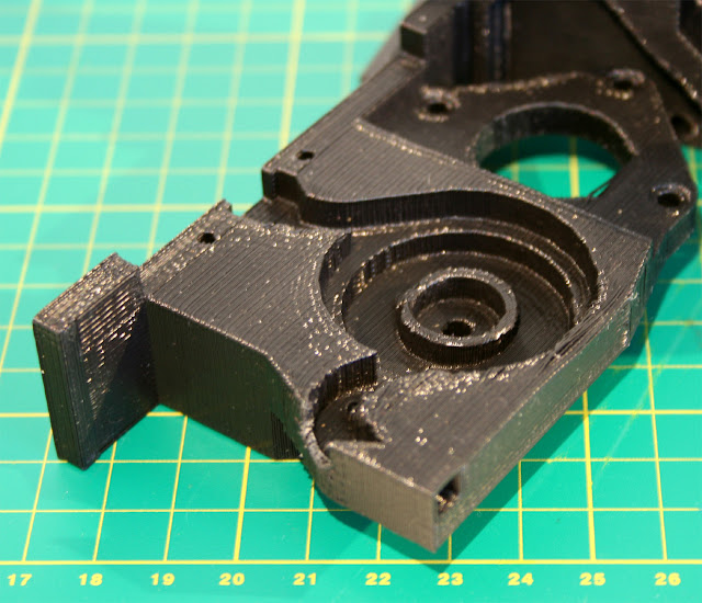
Woodfill fine motor mounts using a 0.5mm nozzle and a lower boss made from Woodfill Coarse and a 0.8mm nozzle - These are in the unfinished (un-varnished state)
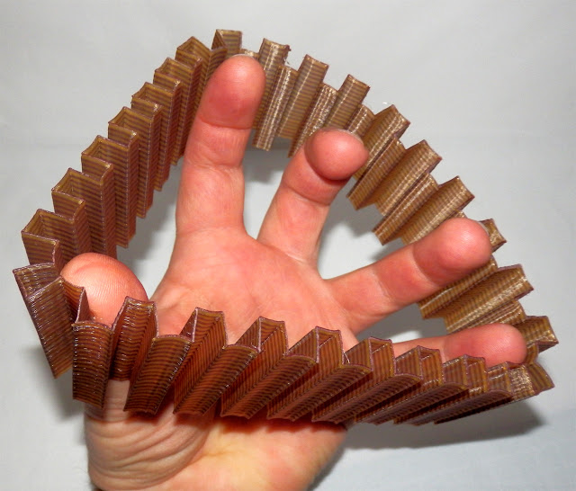
It's a remarkably strong material, but can be carved, sanded and smoothed. The Varnish does not really add any more strength, but helps to seal the wood, giving a slight sheen to the end finish.
Very smooth printing with Woodfill fine - printed at 60mm/sec
Super close-up of Woodfill fine - you can see the plastic content, the fine wood fiber is also visible.
Woodfill Coarse (0.8mm nozzle) fast printing, a more chunky sandy-finish.
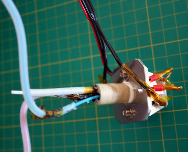
Hollow Bamboo - you can still run the motor wires in the center.
It was so strong I decided to make an entire 3DR out of it. - Frame built - about to add the carriages and electronics.
I'm really impressed with the Bamboo canes, very strong and light weight, I re-designed the printed parts with 15mm holes, to my surprise when I went to buy Bamboo canes they were exactly 15mm in diameter, not a single bit of sanding they just fitted and are held in place with some 10mm M3 bolts - all three sections of Bamboo in this machine cost me just £0.18p ($0.25) in total.
You can also varnish Woodfill, sand it and carve it. as mentioned it's available in two sizes, fine for use in a 0.4mm nozzle (Note:- I actually found it works better in a 0.5mm nozzle, I had more consistent results and no jamming)
And the Coarse material that needs a 0.8mm nozzle or bigger. This prints a little lighter, giving me a two-tone look to the machine.
3D printing news - So many things are going on at the moment, this industry is exploding with new ideas and interest from all over the world, it's a very exciting time...
All this commercial success is attracting the attention of the big players as
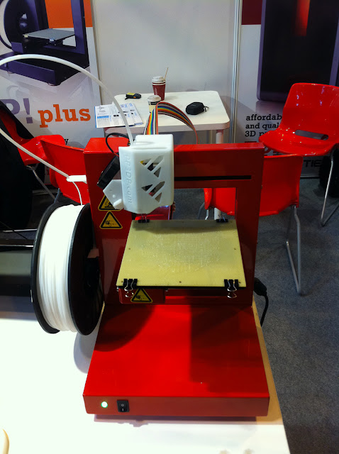
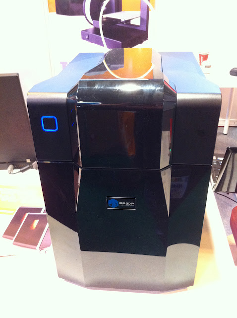
Afinia recently found out. The Afinia / Up! printer was designed in China by PP3PD, part of Delta. Stratasys have issued a law suit to Afinia (Who licensed and re-engineered the Up! printer for approval and sale in America) for infringement of their patents. If you are interested in following or many issues this has thrown up discussions are going on in the
RepRap Forum here and the
PP3PD forum here.Stratasys and Delta seem to have had some issues in the past with each other, so it's not a great surprise this has happened.
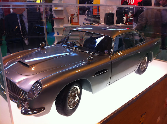
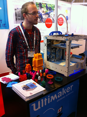
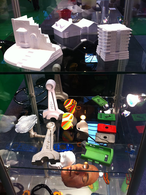
3D PrintShow London - I visited the 3D PrintShow in London in November, it was quite a contrast from the
TCTShow, more glitz and glamour with a focus on the consumer and 3D Printed object rather than the industry as a whole.
It needs a separate blog post really (which I will try to do) -
And do read Rachel's review of the 3D Printshow here, and how could I forget
Christopher Barnatt who has done a video of the show.Slic3r - A new version of
Slic3r is out - V1.0.RC1 - updates to support structure and many other tweaks.
RepRapPro Ltd. - The Team over at RepRapPro have now launched a much anticipated new RepRap machine, the called Ormerod, after the entomologist Eleanor Ormerod. The new 3D printer is a wonderful and elegant minimalist design, still self-replicating in nature and amazingly easy to assemble.
Along with the new printer comes some really fantastic electronics that can not only be driven from a web-page (Instead of using Pronterface for example) but are ARM (Arduino Due) compatible. Nophead and Think3DPrint3D assisted with the electronics development and it looks a real gem of a board, and all of it's open-source, much more detail over on the RepRapPro Website here. Very exciting.
Sustainable and ethical filament production - On the way back from the 3D Printshow in London, I felt the need to start some discussions about 3D printing plastic and the way it's created, used, and recycled. I put up an article over on
3DPrintingIndustry here if you are interested to read more about the work William Hoyle and techfortrade are doing.
On the same subject,
Sadaf Atarod also looks at the longer-term view of plastic recycling herePractical 3D printing - I'm planning an article on real-world and practical 3D printing for the RepRapMagazine, if you have any examples of things you have done to assist you in your daily lives or for someone else. especially if the object you made was custom or specifically designed where an equivalent from a shop was not suitable for whatever reason. -
A thread is started over on the RepRap Forum if you want to add any notes or images of designs or prints you have done in this area, will be featured in a future issue of the RepRap Magazine. Many thanks.
As an example - Around my house are 3D printer post toppers (because I could not buy ones of that size) and 3D printed 20MPH Road Signs (Again, could not buy a rigid one the correct size, and I didn't want just a sticker).
Kraken! - Water cooled 4-head block
Major over the top water-cooling ! but it'll allow for some future expansion ;)
The mighty water cooled bowden-fed Kraken is starting to raise a tentacle or four, I have it partially up and running, just need time to actually print something with all those heads.
(Kraken is now on pre-order with it's creator E3D here)(On a side note - I'm still working on the Hot-ends review, it's getting quite big now! - lots of new hot-ends this year)
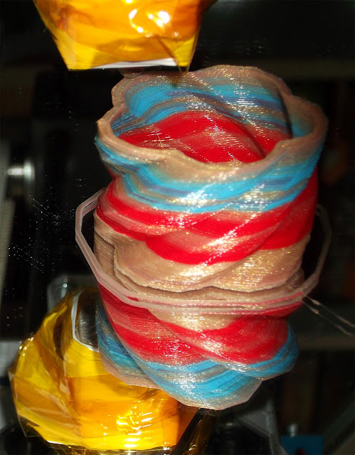
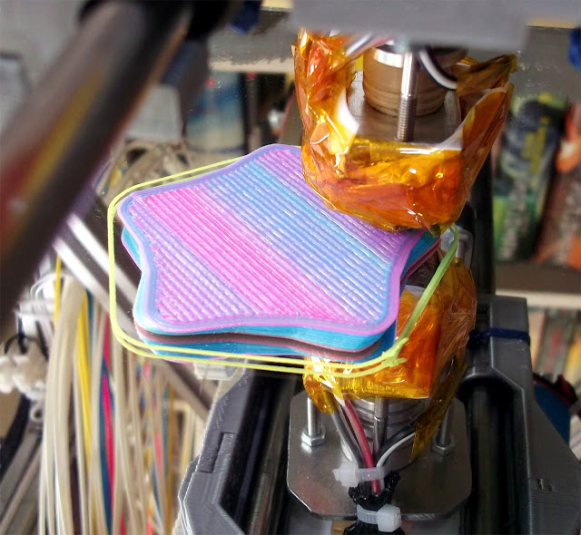
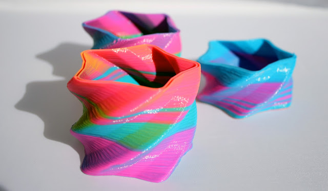
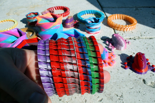
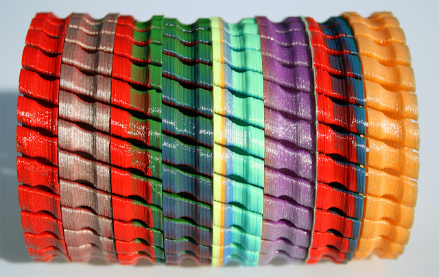
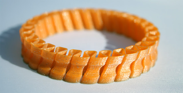
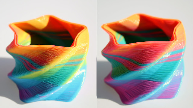
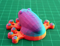
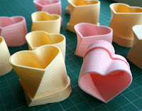
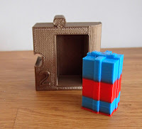
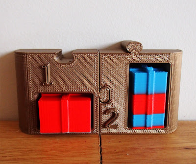
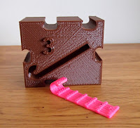
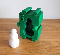
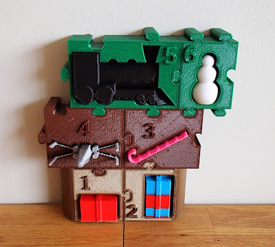
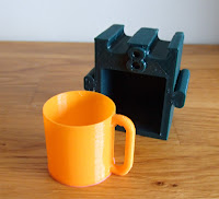
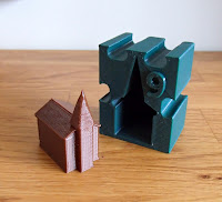
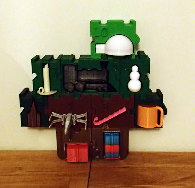
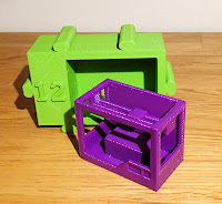
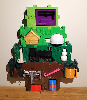
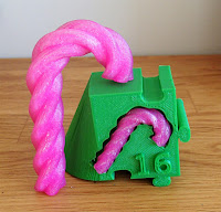
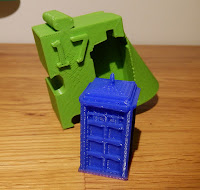
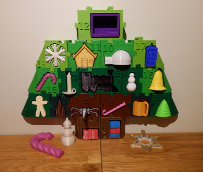
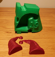
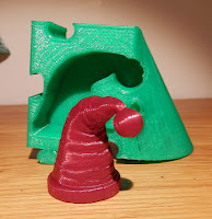
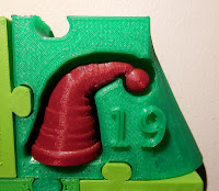
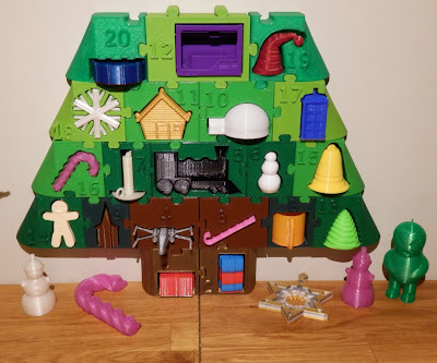
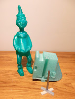
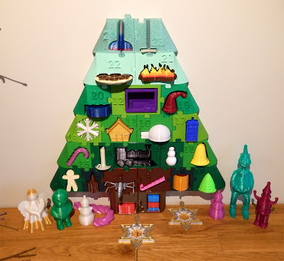
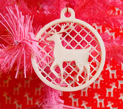
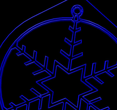
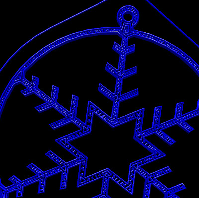
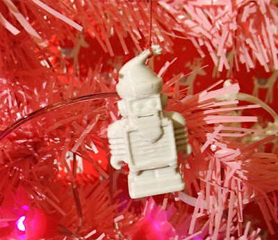
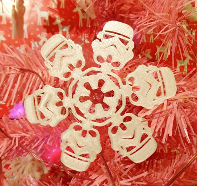
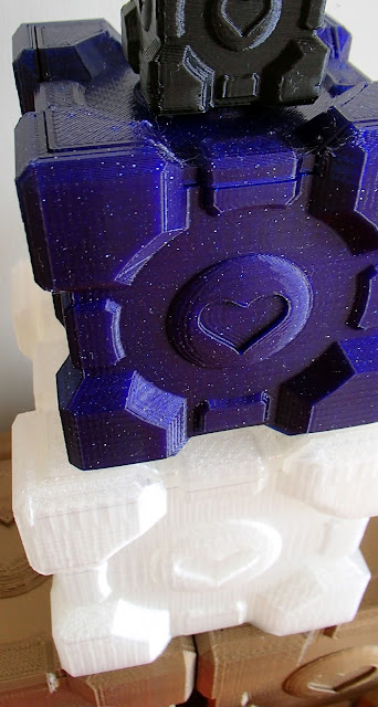
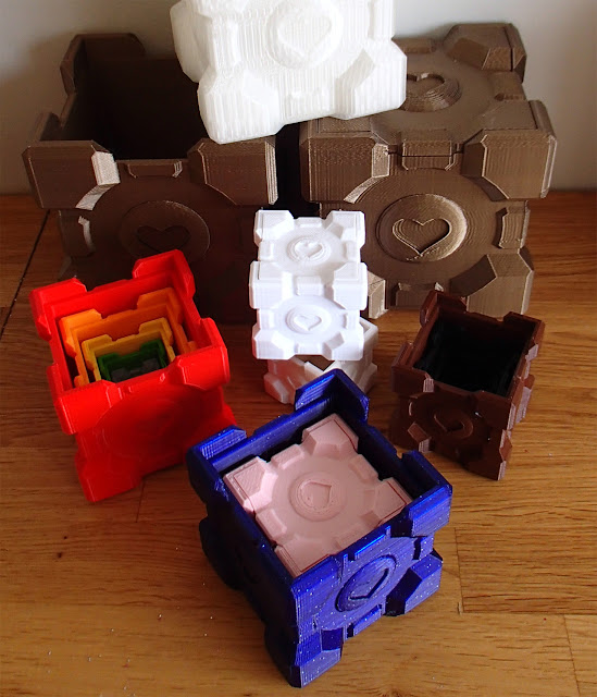
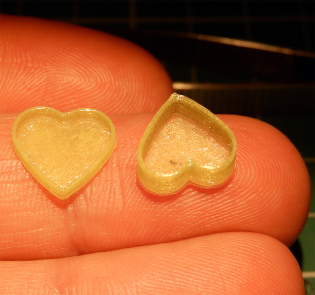
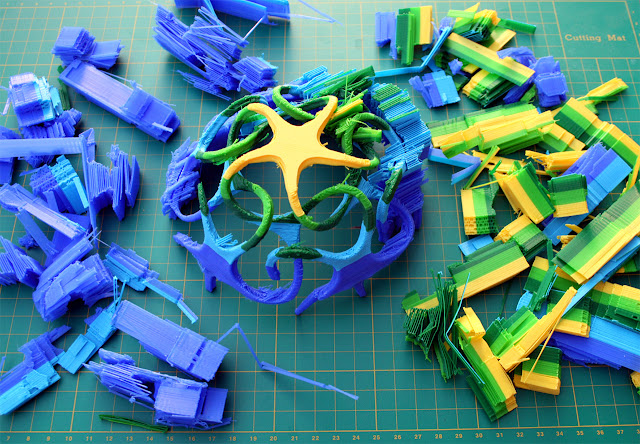
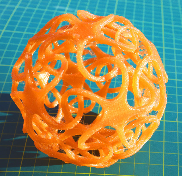
It's Christmas ! (Season's greetings everyone) - My kids had a lot of fun printing these Bauble's on 'their' 3DR printer, I think we have a lot more to come...
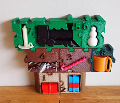
One responsible way to use your 3D printing plastic is by sharing a little love and the joy of making with friends and family. Lots of cool Christmas objects are going up on Thingiverse and Youmaging - if you want a head-start do take a look at the great
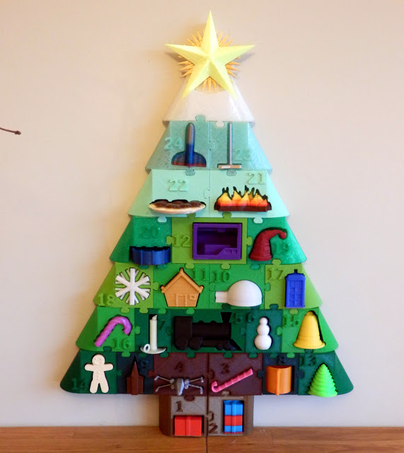
Advent countdown by Faberdashery here and
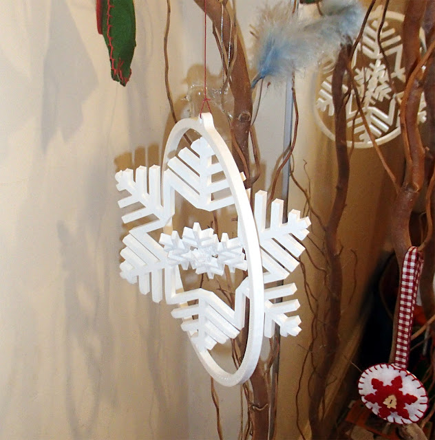
MakeALot's Snowflake Bauble here And let's not forget the fun we had last Christmas with the printable
Advent calendar by Peter leppikWishing you wonderful seasons greetings if you celebrate it, see you next time.
Rich.