This post is about printing small layers in Slic3r. It's Part 3 of my Slic3r Overview, I hope it's useful.
In Part 1 we setup some Slic3r settings and performed the important Extruder Setup
Part 2 looked at print speeds, filament dimensions, heated beds and did some basic printing.
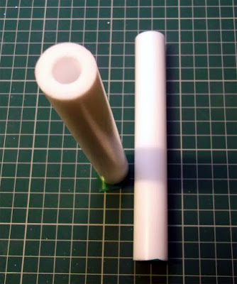
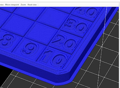
After Neil Underwood's recent Blog post about ultra-small layers I decided I really needed to experiment, but I wanted to see and compare for myself at what layer height it was pointless to go lower. I didn't fancy messing about with getting my bet 'that' level so I made and sliced a simple object at many different layer heights and combined the Gcode so I could have one compare print.
This was printed at a constant speed of 50mm/Sec, it's just a double wall (1mm) triangle column, I could have changed speed for the different layers, but as a starting test I wanted to see what happened at a constant speed and ever lowering layers.
It all sounded so easy.... ultra low level printing is not at all as easy as it first seems.
Fine Layers Test 1 -
Slic3r Makes it easy to play with different layer heights, it's a good way to experiment and test if both your calibration and machine setup is really good.
Before I start a multi-hour print of something I wanted to make sure low layers would work and look good on my machine and be worth the time and trouble -
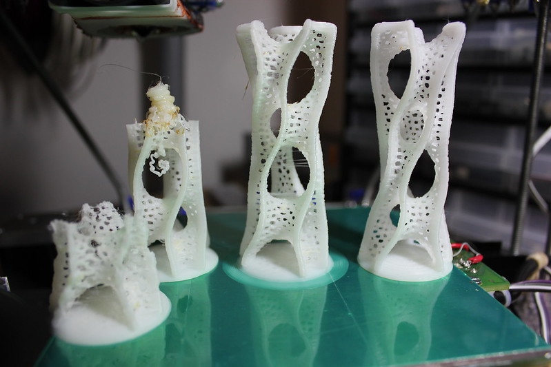
Here is a solid wall multi-layer simple triangular cylinder where the Gcode changes down in height every 10mm starting at 0.3mm (300 microns - my normal print height) going down to 0.04mm (40 microns) after that I stopped the print as something was clearly upsetting the surface of the print and making it lower quality.
I started to see 'bobbles' on the surface at the 0.05mm height, I first thought the temperature was too high, so I experimented with lowering it, that seemed to make the problem no better, maybe even worse as you can see below at 170/175 Deg C.
This was my very first very-low-layer print and I obviously it had some issues...
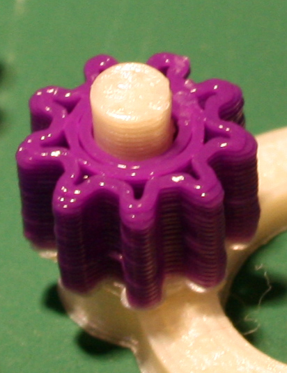
So I started thinking that because the hot nozzle is constantly going over the same plastic and causing constant re-melting of the surface maybe causing the effect seen below - for the want of a better way to describe it - 'heat-friction-bobbles' on the sides of the object. The white flecks are quite fine and many can be rubbed off.
![]()
![]()
![]()
![]()
![]()
![]()
![]()
![]()
![]()
![]()
![]()
![]()
![]()
![]()
![]()
![]()
![]()
![]()
![]()
![]()
![]()
![]()
![]()
![]()
![]()
![]()
![]()
![]()
In Part 1 we setup some Slic3r settings and performed the important Extruder Setup
Part 2 looked at print speeds, filament dimensions, heated beds and did some basic printing.
After Neil Underwood's recent Blog post about ultra-small layers I decided I really needed to experiment, but I wanted to see and compare for myself at what layer height it was pointless to go lower. I didn't fancy messing about with getting my bet 'that' level so I made and sliced a simple object at many different layer heights and combined the Gcode so I could have one compare print.
This was printed at a constant speed of 50mm/Sec, it's just a double wall (1mm) triangle column, I could have changed speed for the different layers, but as a starting test I wanted to see what happened at a constant speed and ever lowering layers.
It all sounded so easy.... ultra low level printing is not at all as easy as it first seems.
Fine Layers Test 1 -
Slic3r Makes it easy to play with different layer heights, it's a good way to experiment and test if both your calibration and machine setup is really good.
Before I start a multi-hour print of something I wanted to make sure low layers would work and look good on my machine and be worth the time and trouble -
Here is a solid wall multi-layer simple triangular cylinder where the Gcode changes down in height every 10mm starting at 0.3mm (300 microns - my normal print height) going down to 0.04mm (40 microns) after that I stopped the print as something was clearly upsetting the surface of the print and making it lower quality.
I started to see 'bobbles' on the surface at the 0.05mm height, I first thought the temperature was too high, so I experimented with lowering it, that seemed to make the problem no better, maybe even worse as you can see below at 170/175 Deg C.
This was my very first very-low-layer print and I obviously it had some issues...
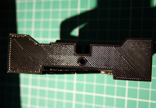
So I started thinking that because the hot nozzle is constantly going over the same plastic and causing constant re-melting of the surface maybe causing the effect seen below - for the want of a better way to describe it - 'heat-friction-bobbles' on the sides of the object. The white flecks are quite fine and many can be rubbed off.

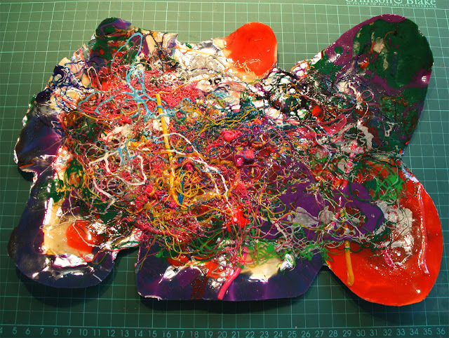
I have increased brightness and contrast on this picture so it shows every flaw and defect.
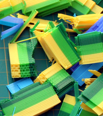
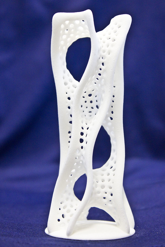
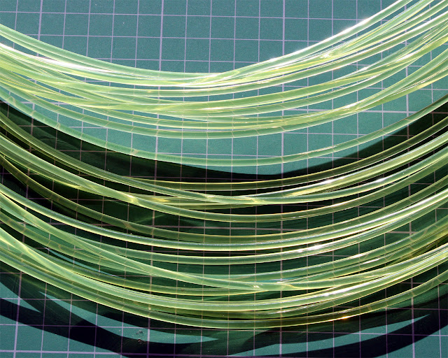
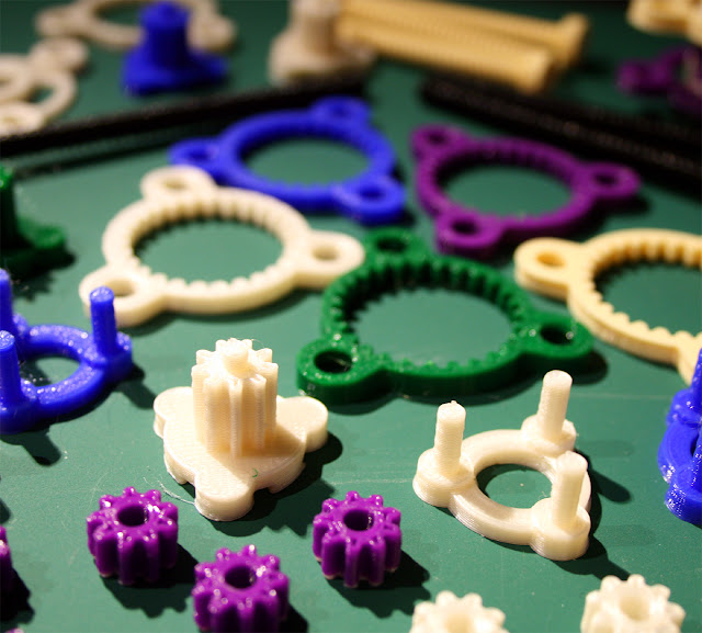
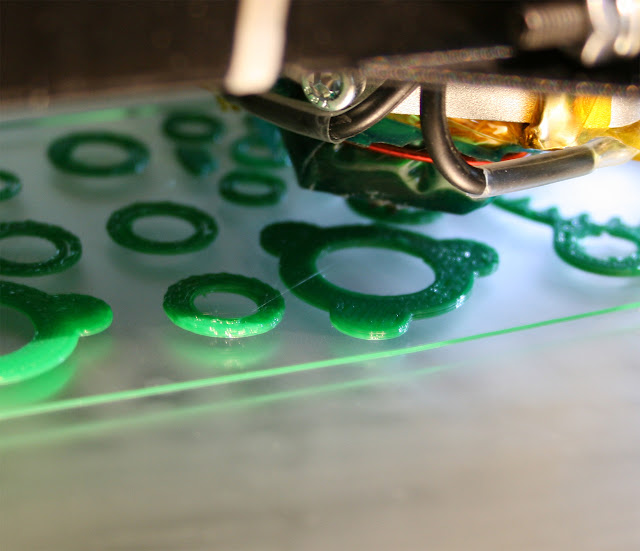
For reference the print material in all these tests is Greenery Green PLA from Faberdashery, it's highly dimensionally accurate and is also very nice to photograph.

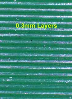
For reference - The test object printed at 0.3mm all the way up.
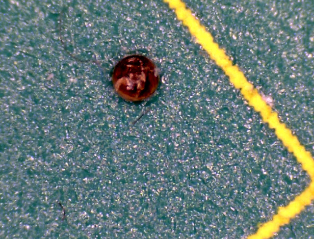
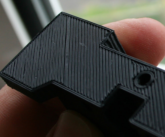
I decided to take a closer look at every layer height change under the microscope -
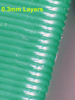
0.3mm flat face and corner.


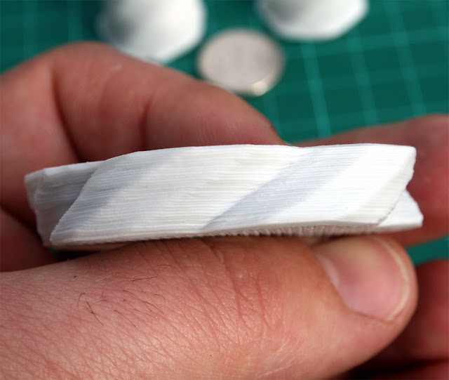
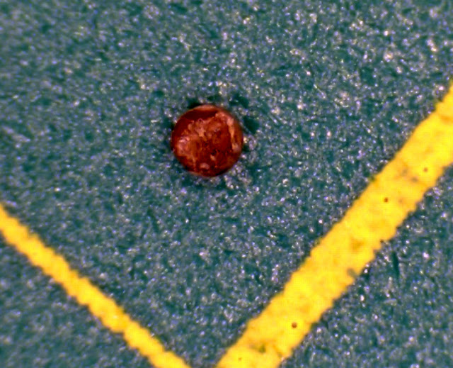
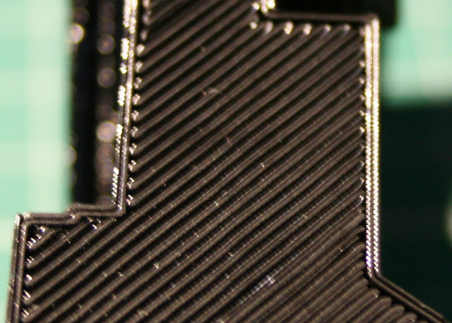
At the 0.3mm to 0.2mm layer change point, interestingly Slic3r changed build direction of travel when the layer height change to 0.2mm, in the picture you can see the effect above.
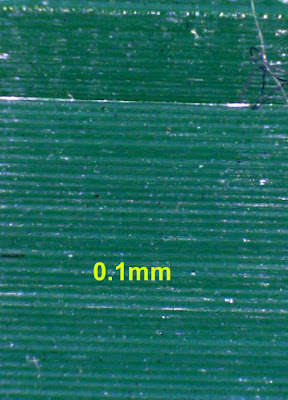
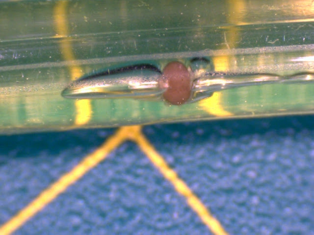
0.1mm

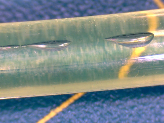
0.05mm

0.04mm

Clearly things are getting worse as layer height decreases.
I had produced Gcode all the way down to 0.01mm, but I didn't print any lower for this test.
Could it be a calibration issue?, too much plastic? or maybe a mechanical limit?
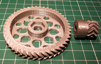
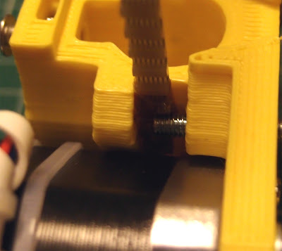
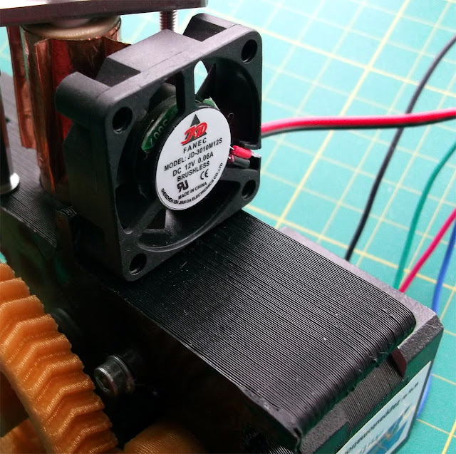
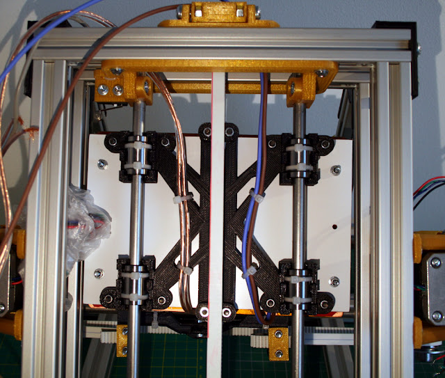
The Z axis on this machine is set to 8x micro-stepping, using an M8 rod this gives 1280 motor steps per mm - 0.05mm is still 64 motor steps, so Z resolution should be good enough.
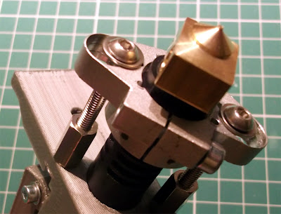
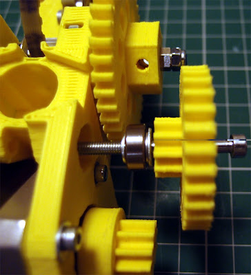
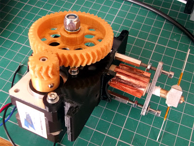
Even though I'm also only using 8x micro-stepping on the extruder it's a Wade style geared design so also has plenty of steps to ensure plastic is flowing at a constant rate even with very small levels of plastic extrusion.
I was also concerned about my choice of test object, being a triangle with solid walls the point requires much less volume of plastic, and I started to think the corners were getting over-stuffed - I'm not sure how Slic3r calculates this compared to Skeinforge, but maybe performing this test again with a Cylinder or Octagon will shape object would help see if this is why I'm seeing this issue...
I was very tempted to publish the Blog post at this point and ask for help and advice, but I wanted to know why my machine setup was not looking able to do layer heights as low and as easily as Neil had achieved with Slic3r, so on with the testing.
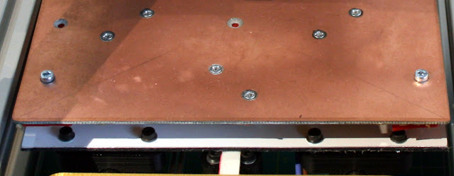
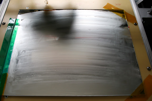
I have never been very happy with using Springs on my print bed, recently I changed to very stiff ones and now with a glass bed I expected no more issues, but it was starting to worry me that the spring-bed could be causing my issues with low layer printing. - I tightened everything ad hard as I could get it (Still using springs) and tried again, the print was better but not significant enough.
Second thoughts - Could it be just the speed of extrusion? maybe the tiny amount of plastic does not have time to form a reliable bond to the layer below - the corner of the object (slower point) is notably more 'solid' and shiny at 0.04mm layer point. - It was time to change something and try again.
Fine Layers Test 2 -
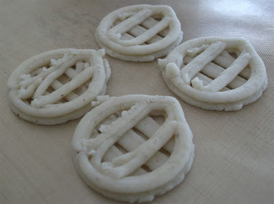
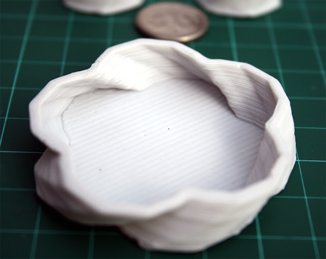
Different shape object - Octagon test -

In an attempt to rule out issues with my first Triangular test object I performed a similar test on an Octagon shape, this time starting at 0.2mm, then 0.1mm and 0.05mm and finally 0.025.

Here is how it came out - I have almost exactly the same problem again.

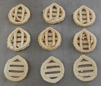
Close-up shows a similar result to the first Triangle tests and as I was printing this slightly faster (60mm/sec) than the triangle (50mm/sec) I was now getting more convinced that speed was the problem with really low layer heights. - Temperature could also be playing a part, but not quite as significant as speed.
With too much temperature (190) the very low layers (0.05 / 0.025) were practically printing by just extruder ooze, when you reduce the temperature to 175 the ooze is minimised and so the print quality also improves.
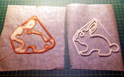
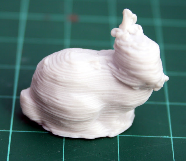
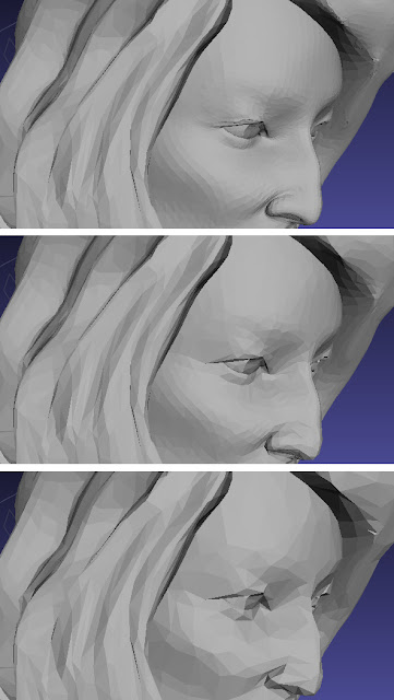
Niel's red pink panther lady did look a little 'furry' in the photo and with no compare or close-ups I was not sure if he had seen the same results as I had. Niel was using 1.75mm ABS, I'm using 3mm PLA, so I didn't expect to get to 0.01mm but I expected better results at 0.05mm and 0.025mm - time to investigate speed and temperature 'v' layer height.
After a few more test prints reducing the temperature to around 175 degrees is about optimal for layers lower than 0.1mm but you still need to reduce speed, see below.

Better with reduction in temperature, but still much too fast for such a low layer height (0.025mm)
This was a final test to see if I could beat my extruder ooze by speeding up the print, I concluded that slowing down was actually the only solution for a clean print at layer heights below 0.05mm.
After reducing the speed to 30mm/sec finally the very low layer prints look good, I think that had finally cracked it - time to print something more interesting.
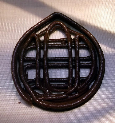
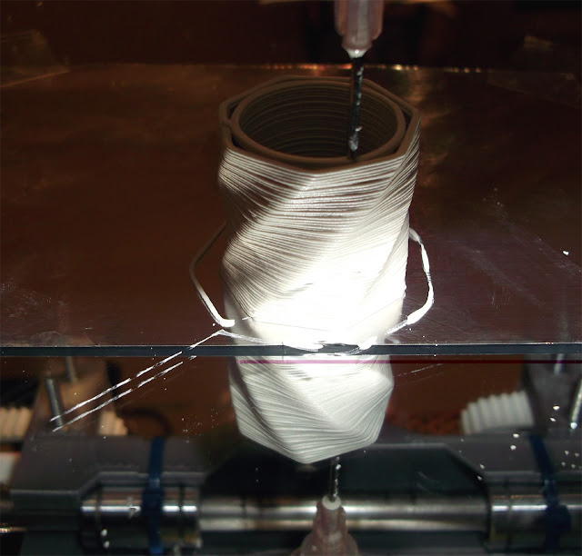
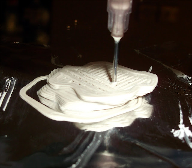
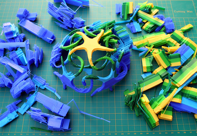
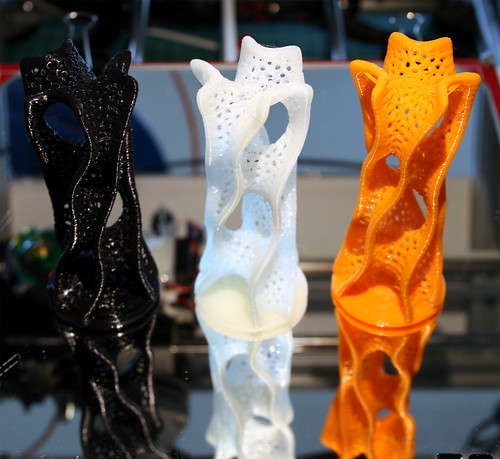
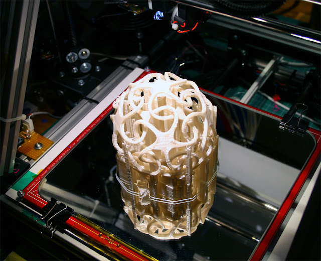
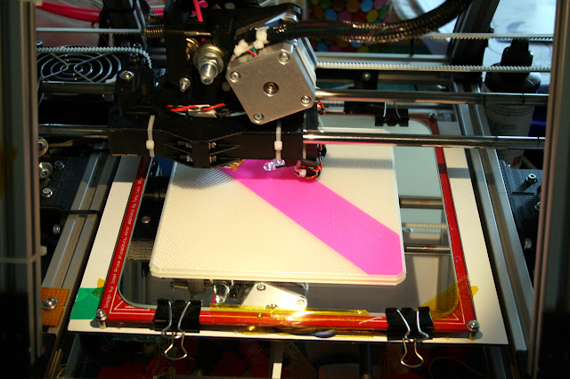
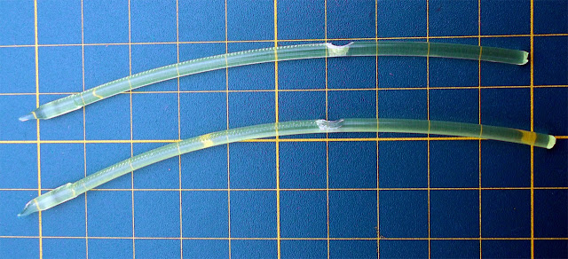
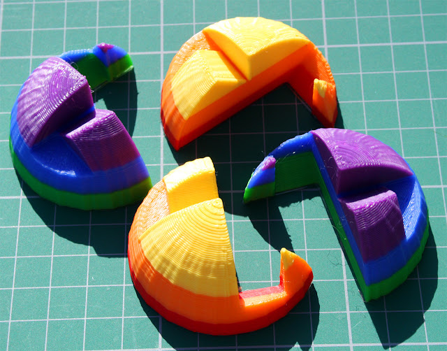
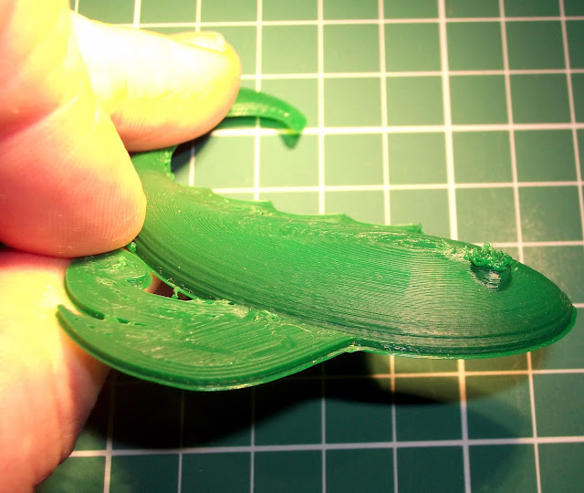
Fine Layers Test 3, Magic Fish -
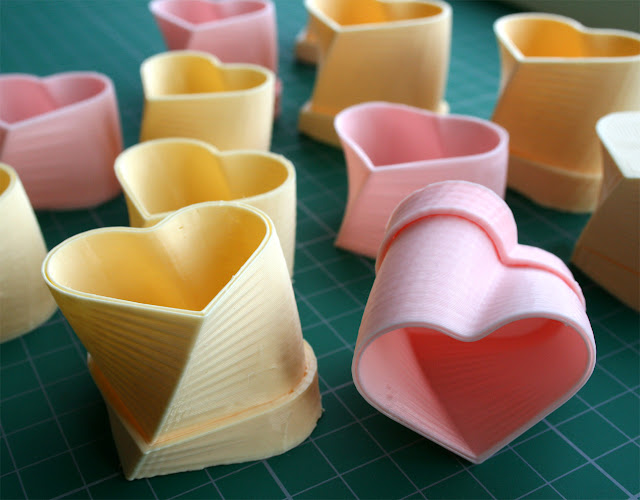
Many of the very low layer prints I have seen (lots of stunning ones from Ultimaker users) are hollow sculptures or usually more vertical prints, I was very keen to try a low but highly domed print as these can be some of the hardest to print nicely and finer layers should make a big difference to the overall quality.
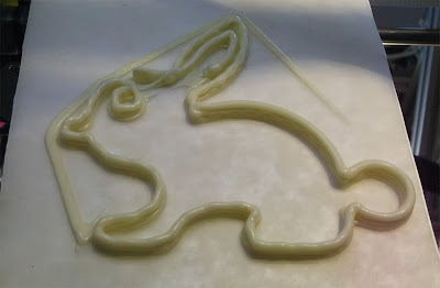
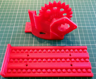
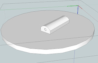
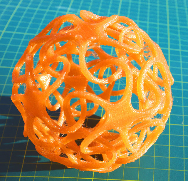
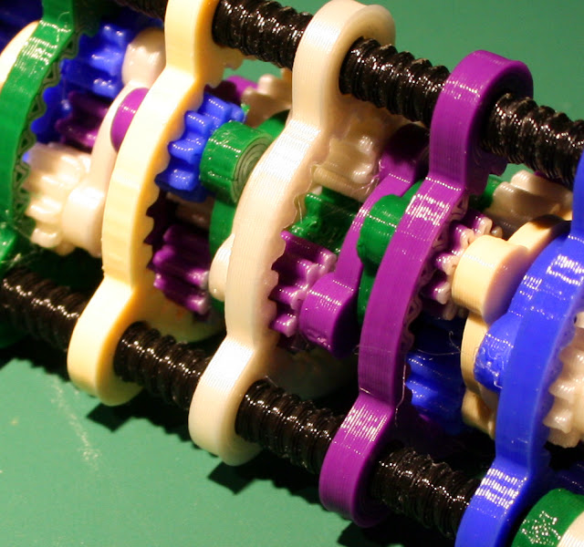
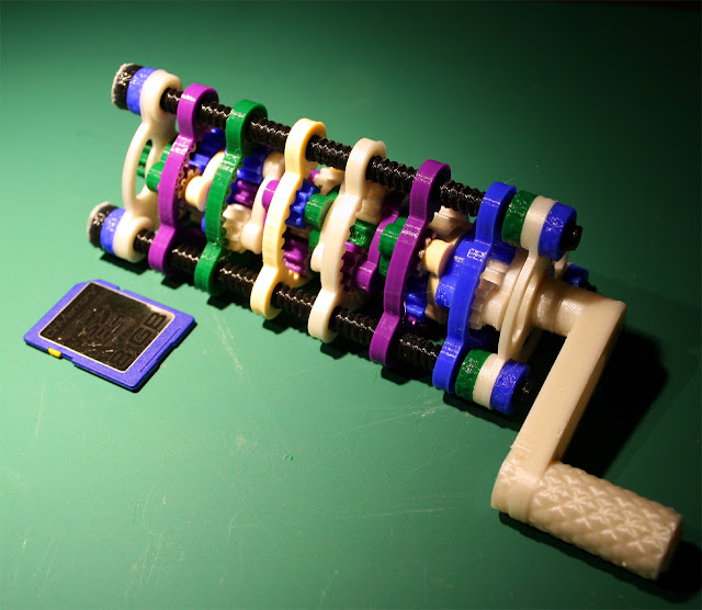
My selected object for the next test was the Magic Fish (Tovervisje) by bpijls this is a really nice part, a little tricky to print well, so a good test of lower layer printing.

7 test fish later I had a good set of settings to help print a low layers.

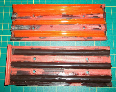
My Reference print @ 0.3mm / 65mm/sec
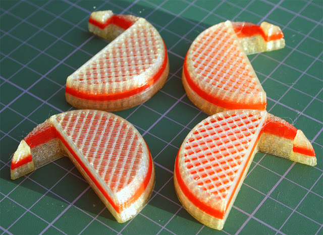
A few close-ups on the tail of the fish as this is an extreme area for both print bridge and overhang.
(All these fish are printed with 25% infill)

Reference print - standard 0.3mm layer height - very quick reasonable print.

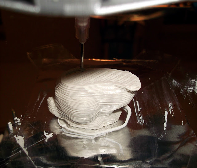
0.2mm layers, 2 perimeters and only 2 solid layers (2 x 0.2 is not enough)
190 Degrees C and 60mm/sec Perimeter and 80mm/sec infill
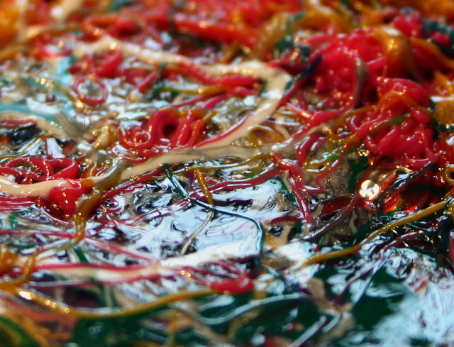
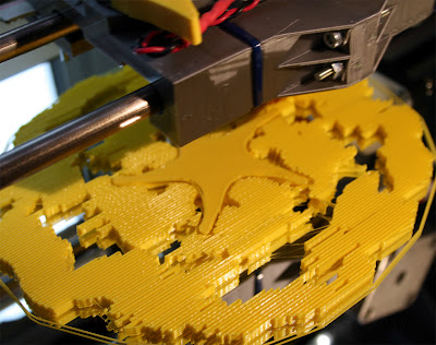
At 0.1mm you need to reduce print speed, reduce print temperature and increase number of solid fill layers...

If you don't reduce speed and increase layers it will end up printing something like this above.


Internal infill still builds ok at 60mm/sec (see above) when at 0.1mm layer height, but at 40mm/sec solid layers also print well on top of loose infill at 0.1mm so again slower is better at low layer heights (below 0.1mm)

You need to experiment to get the number of solid layers and perimeters correct for the type of print you are trying to do, this is so much more critical at very low layer heights than with 'normal' printing.

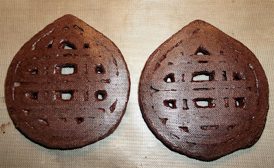
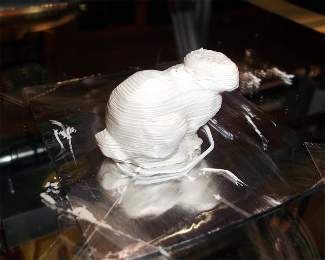
0.1mm layers, 3 perimeters and 4 solid layers.
0.1mm Layers and 40mm/sec - Finally a nice looking fish, the only issue is the eye.

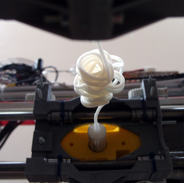
As these are the last few layers to print, Slic3r is not yet slowing down so dumps layers too fast - Slic3r will soon have the ability to limit minimum layer time so this issue should be eliminated.
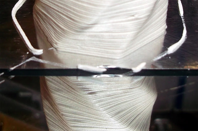
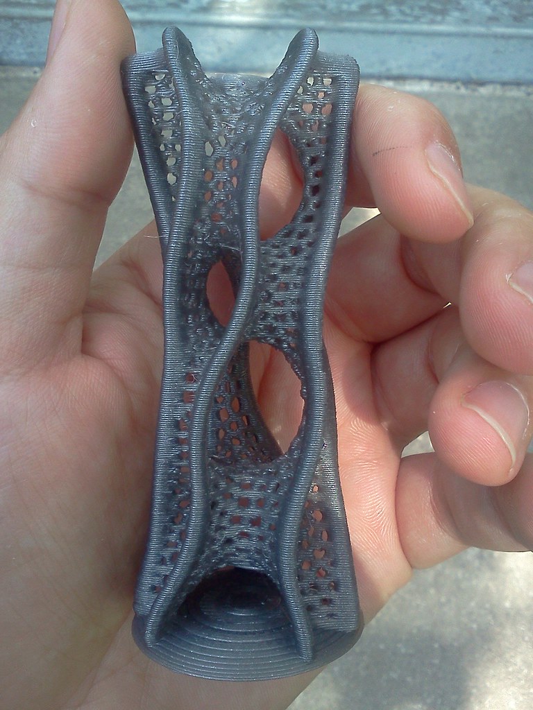
I was just about getting sick of so many fish prints, but just one more - this time at 0.03mm layer height, I didn't note the build time, but it was well over 1 hour to print this little fish- (30mm/sec perimeter and infill)

The first three layers of Gcode are done at 0.2mm to help get the build surface level, then it's two layers of 0.1mm and then all the rest at 30 microns (0.03mm layers).

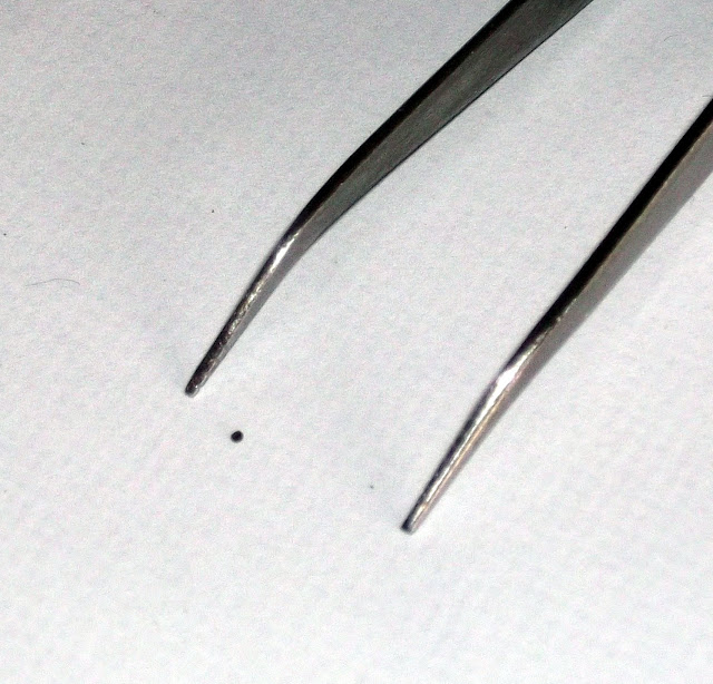
At this layer height I could hardly see the extruder gear moving at all, you need to stare for many seconds to see it's actually extruding. - Higher gearing and 1.75mm filament should help and may also further increase quality for ultra fine layer printing.

I'm still not sure it's worth all the effort going below 0.1mm and I expect I will not go below 0.05mm very much if at all in the future. At least now I know to Slow down and reduce my temperature if I want to go under 0.1mm layers. - I'm really interested in your experiences with low layer printing, do leave a comment below.
Enough of the fish, I hope you give lower layers a try, it will certainly teach you a lot about your printer and among many other things test the quality of your printing material.
Future things to try -
- ABS with very low layers
- 1.75mm Material
- A bigger Extruder gear ratio
- Low layers with Bowden extruders.
- Compare with Skinning in Skeinforge - I have only done a few so far to test the option.
- Test the new Version of Slic3r as soon as it's Released ! :)
Until next time, I hope you liked this Slic3r series, thanks for reading.
Rich.